okt 202018
 

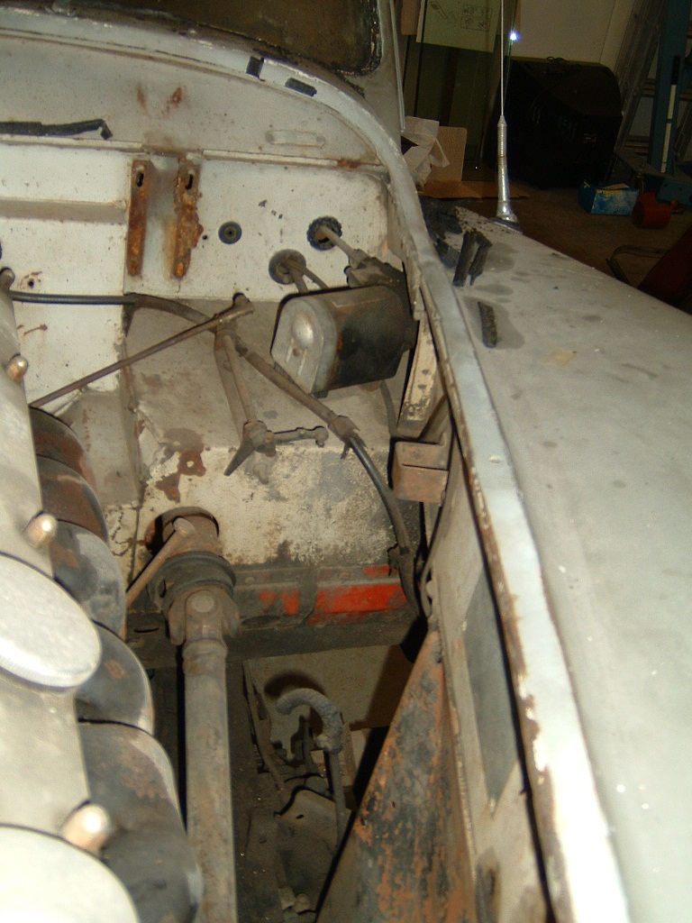
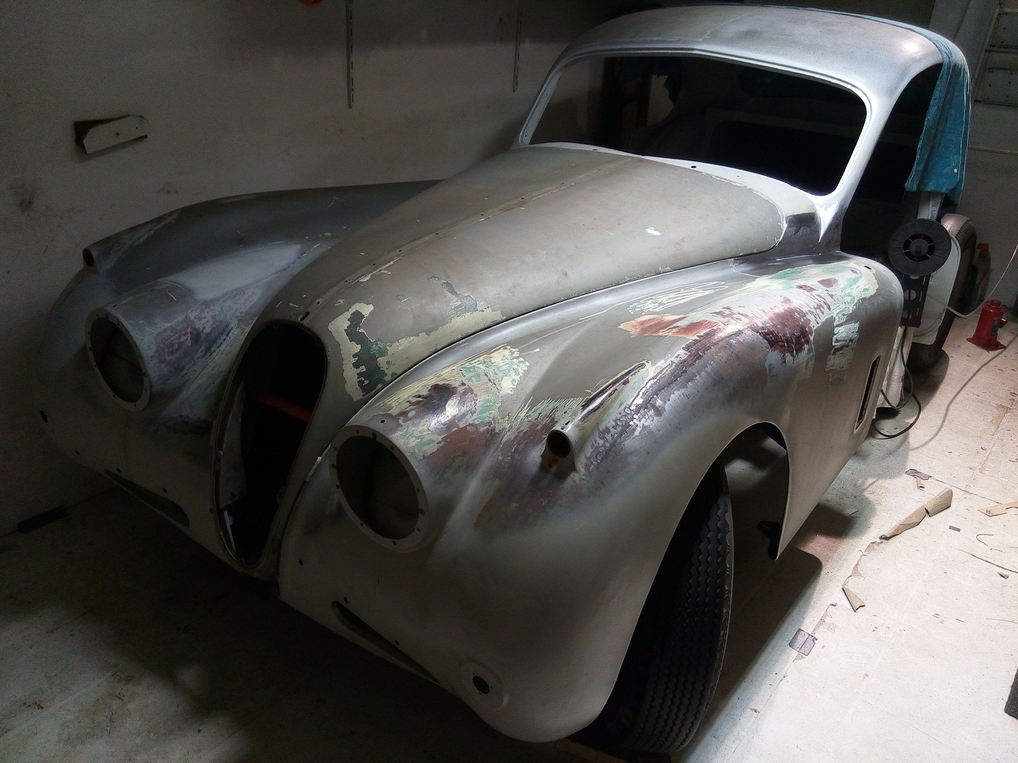
When I bought the car the heater was already removed from the body and placed in one of the many boxes.
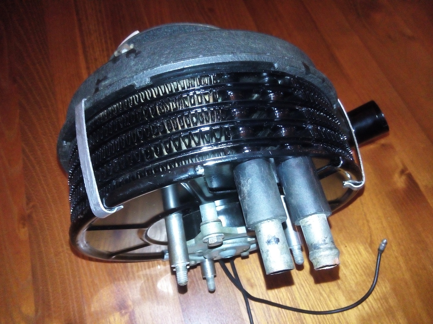
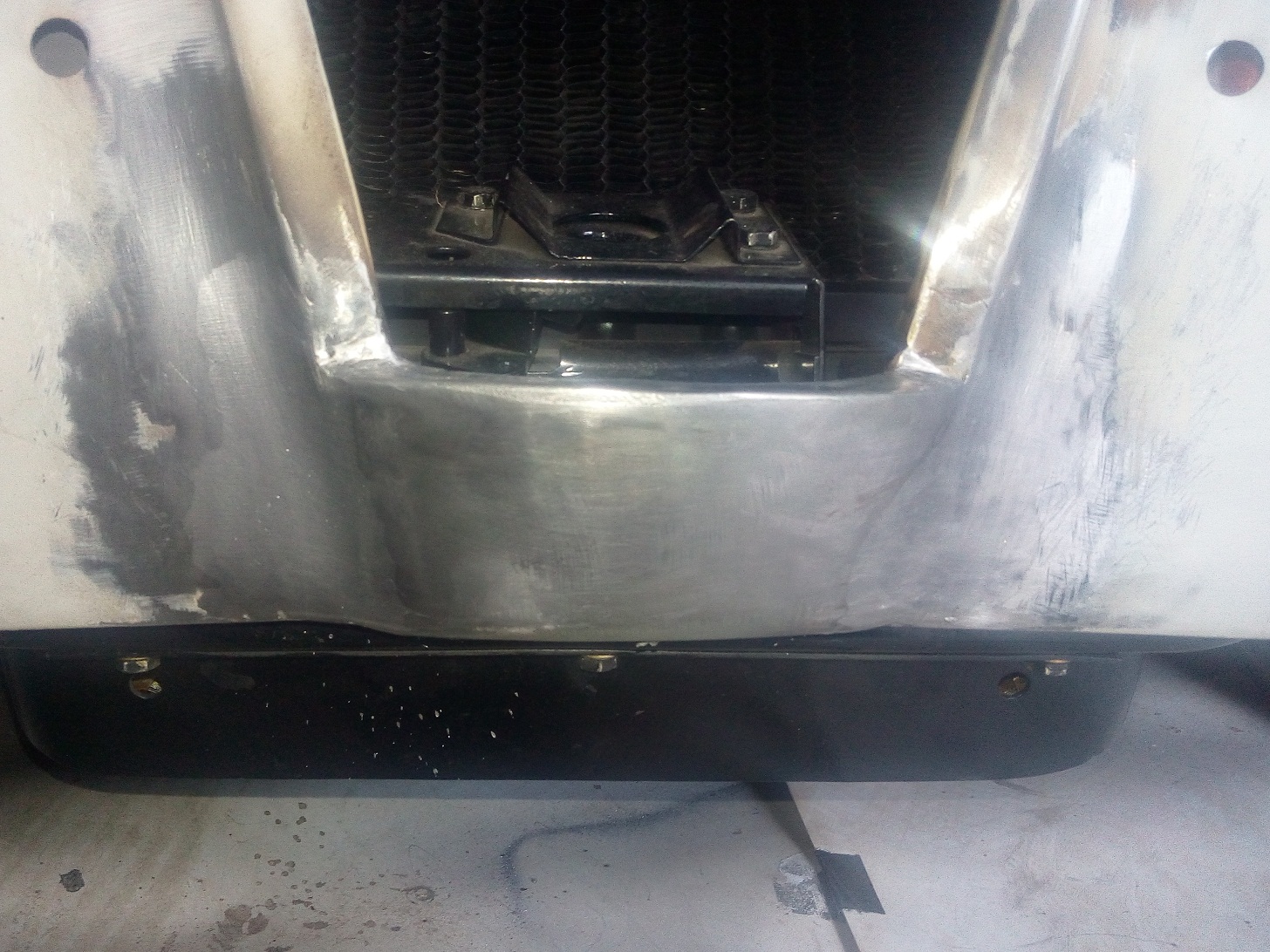
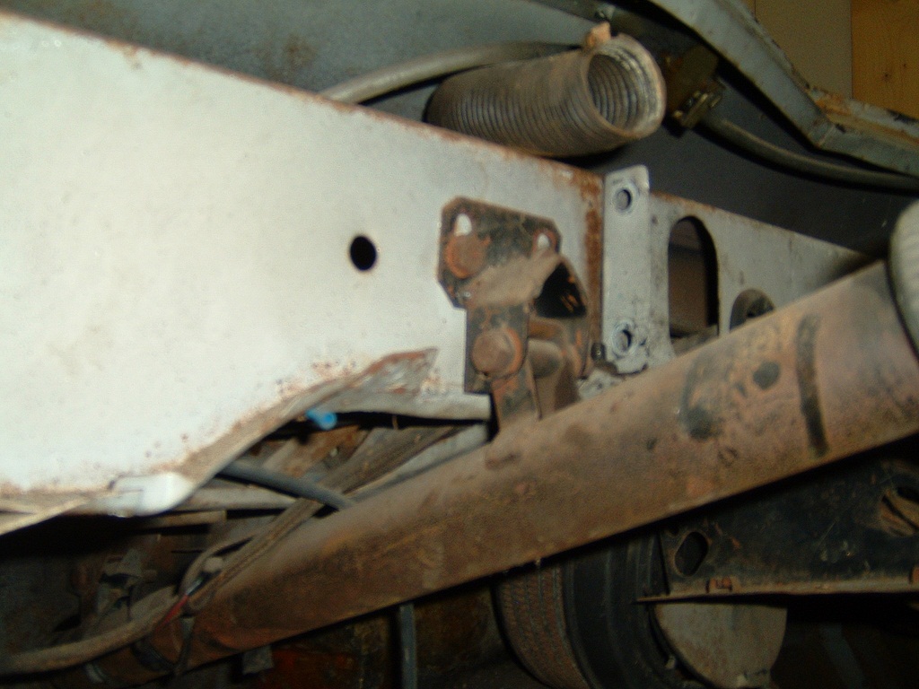
After looking at it in more detail I noticed there was a bit of oxidation visible in the area around the connection pipes.


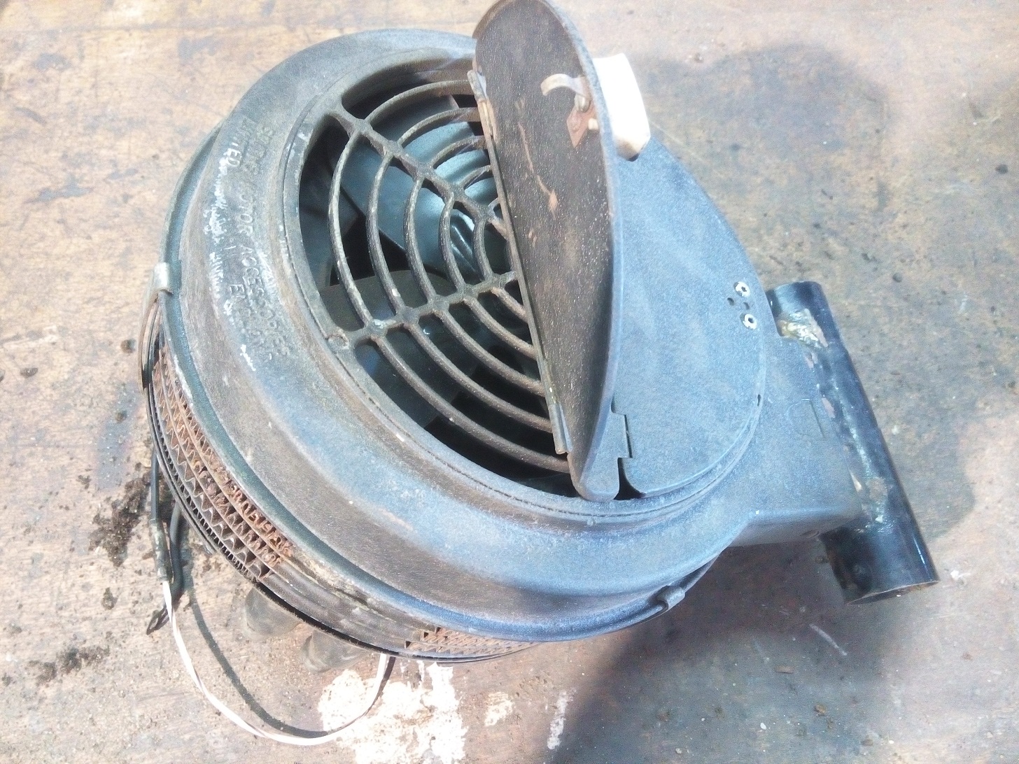
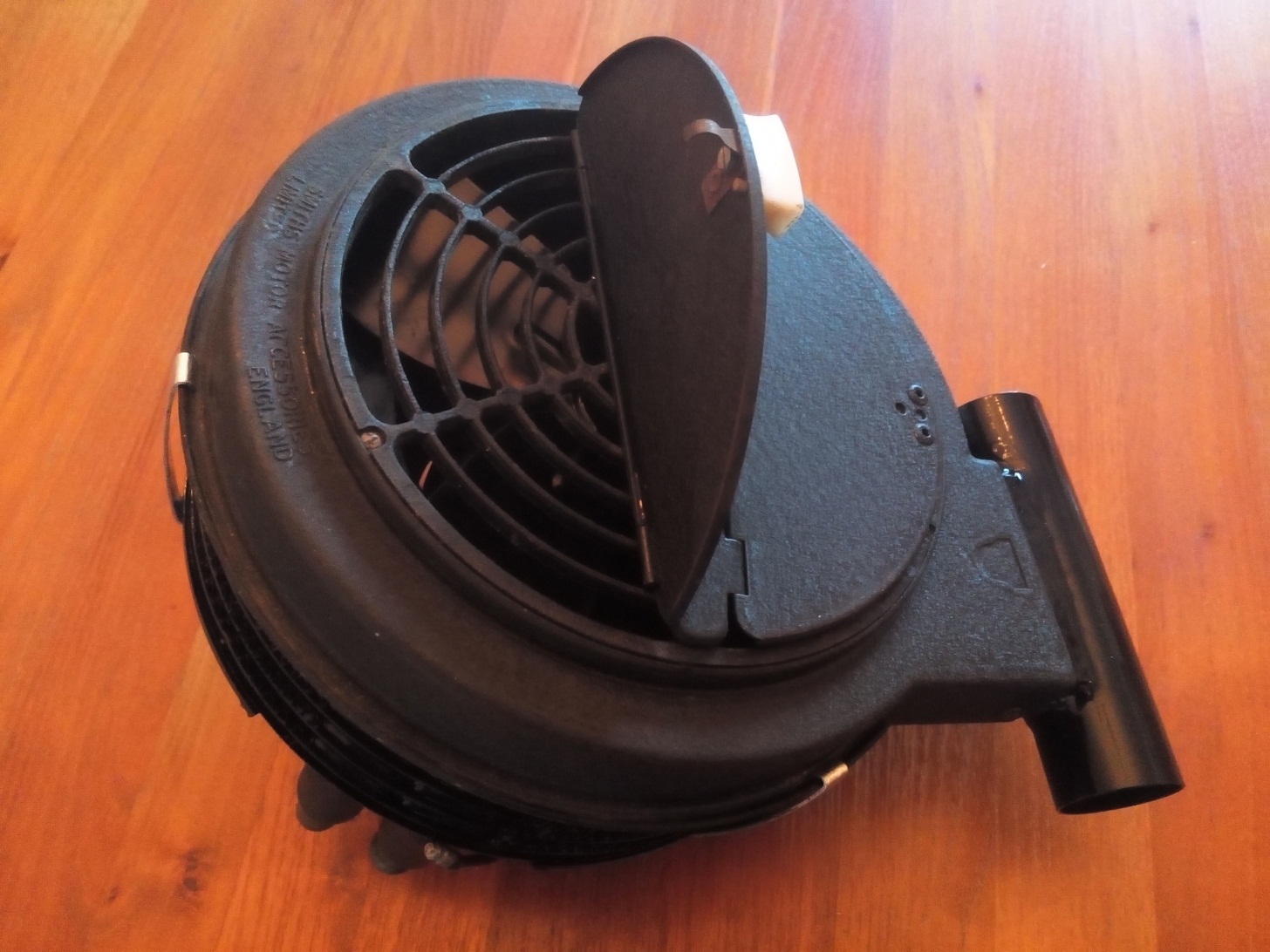
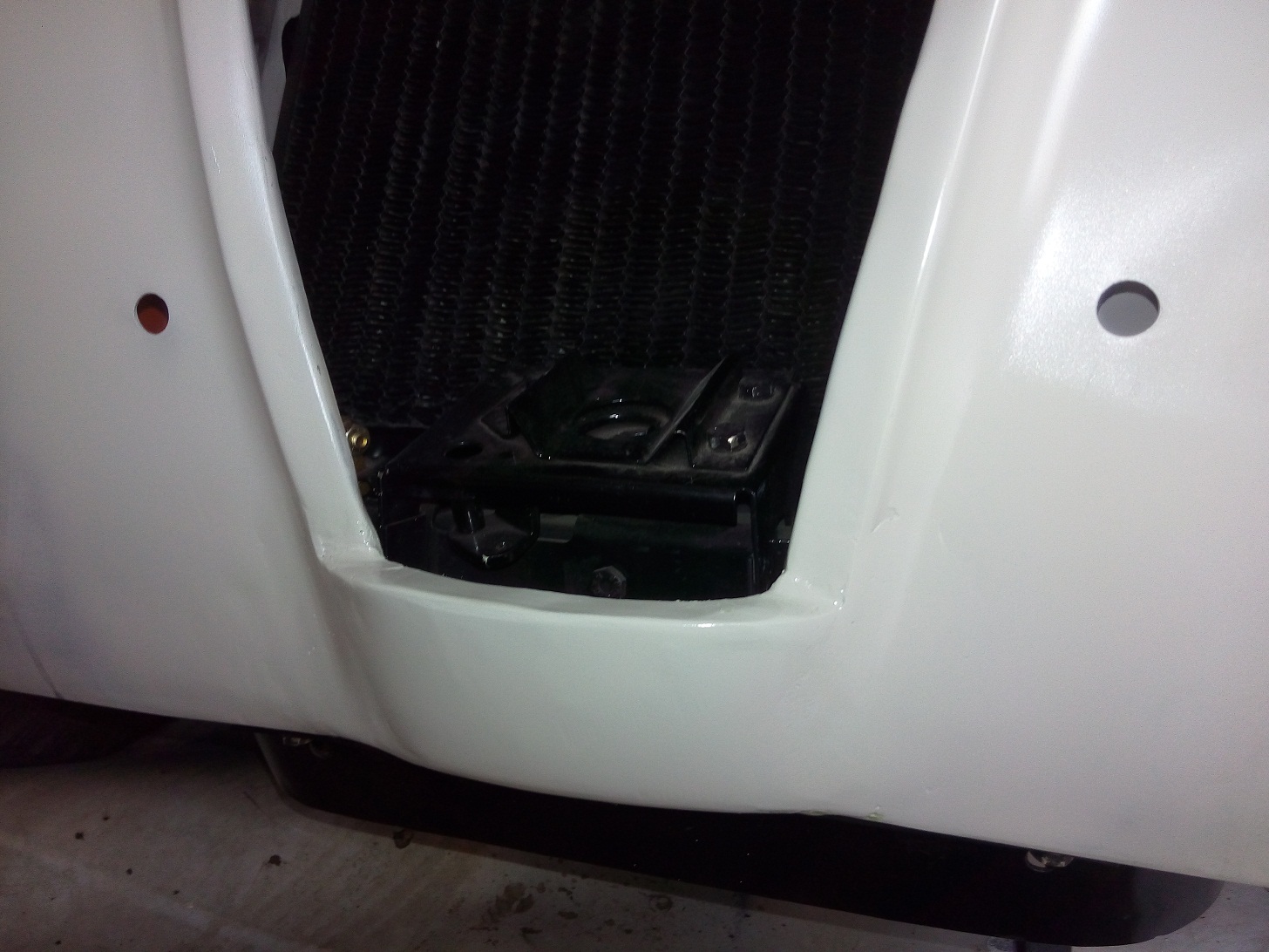
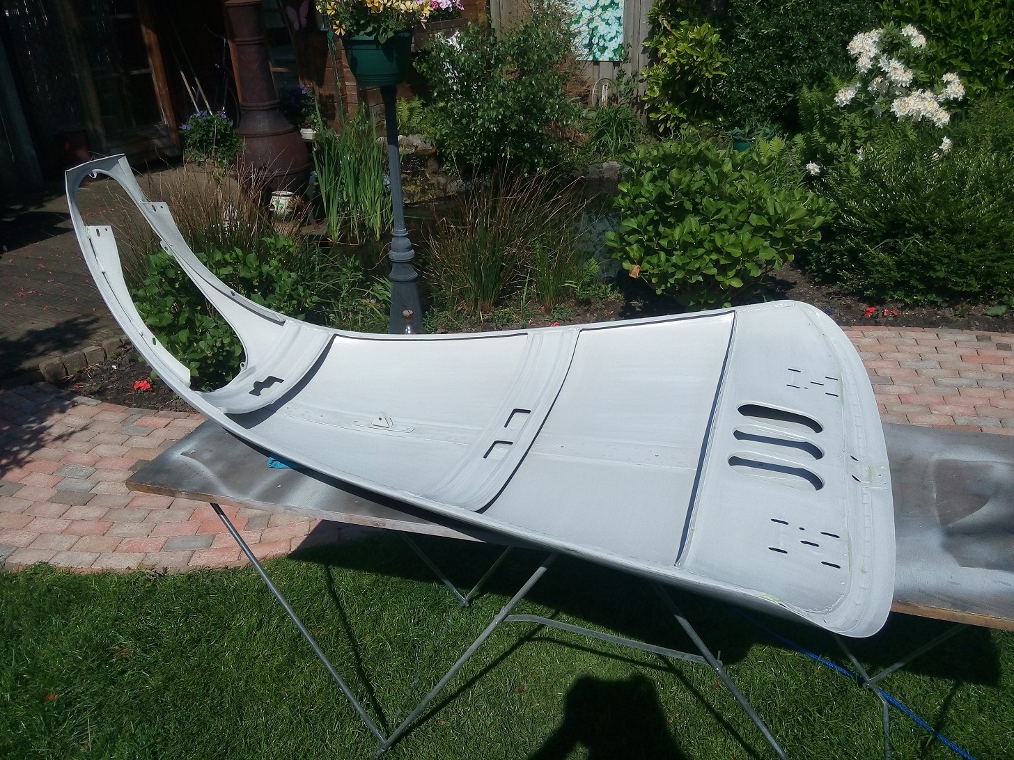
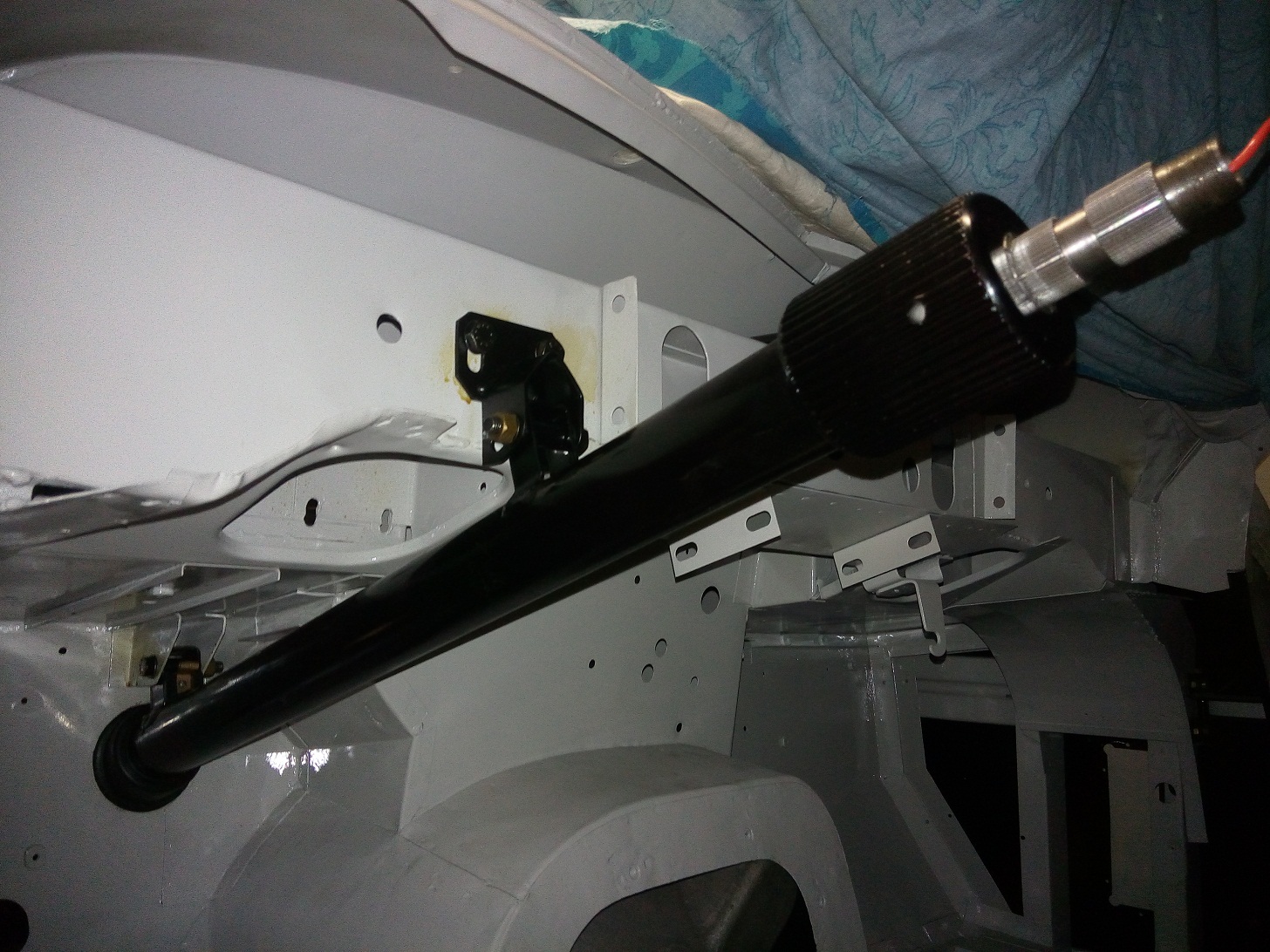
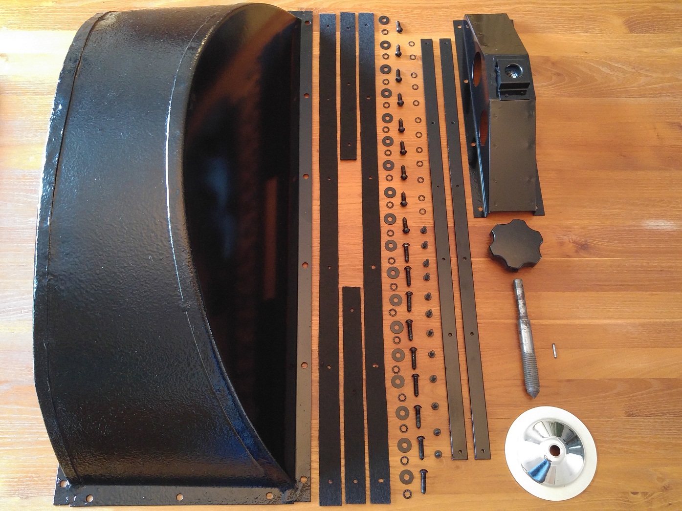
I started with dis-assembling everything. Most parts still looks fine and can be finished with some retouching especially the upper part, which is made of cast aluminium, is finished with special wrinkle paint. The rest of the painted parts are just in gloss black paint. To prevent leakages after installing I pressure test the heater core with 0.5 bar (normally the cool system of the car will not become higher then 4 LBS). Although the heater core has signs of leakage the core is still water tight. After glass beat blasting and cleaning it can be finished with several layers of gloss black paint. The upper part is painted only partly the preserve the numbers painted on it from the factory.

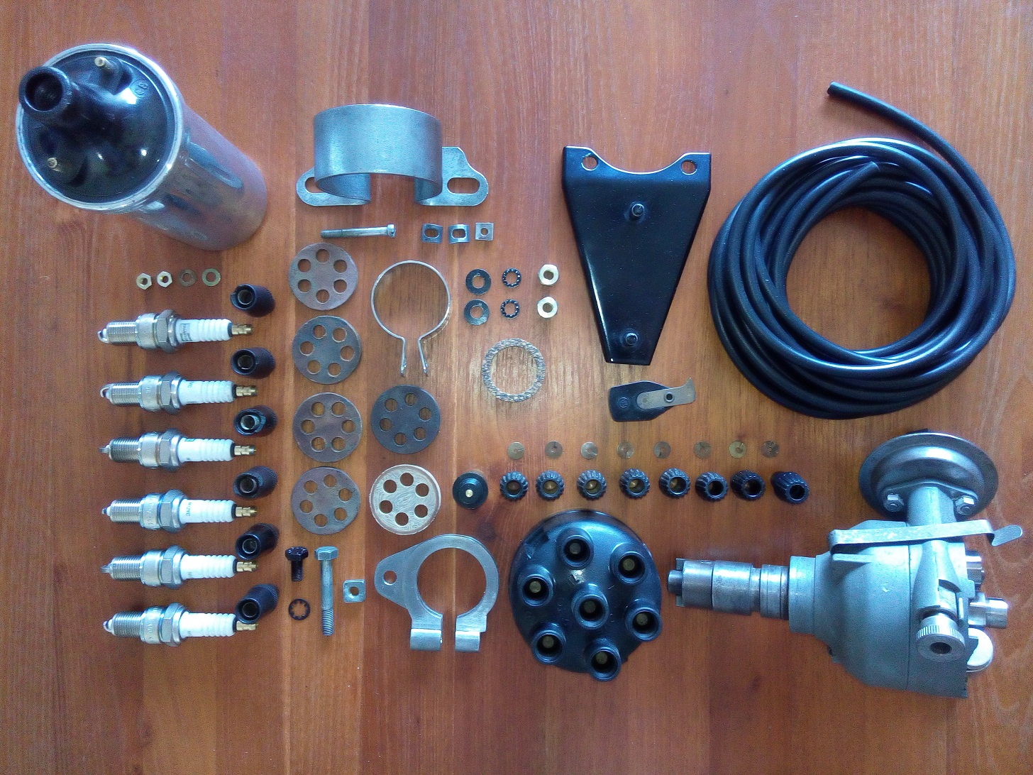
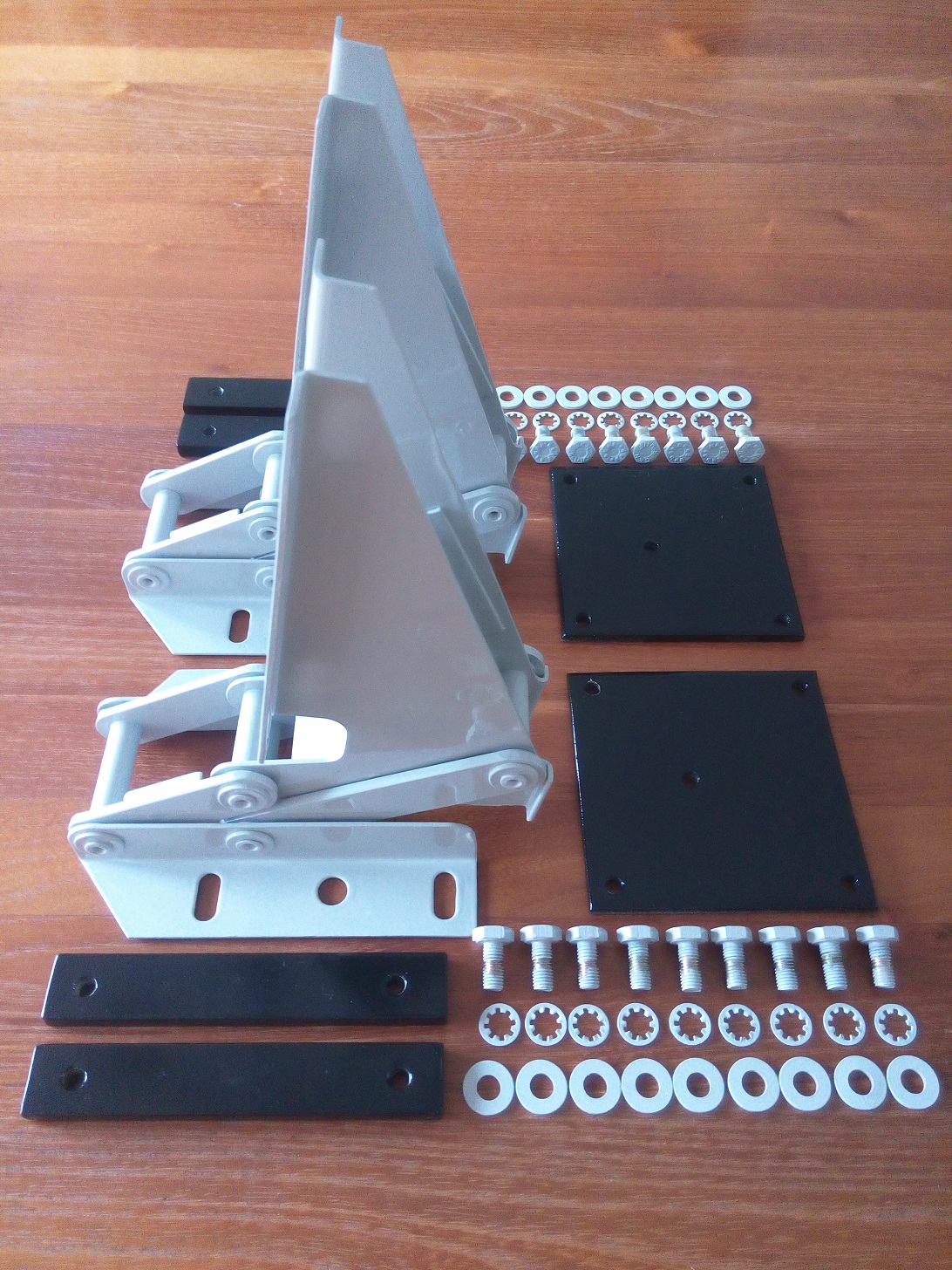
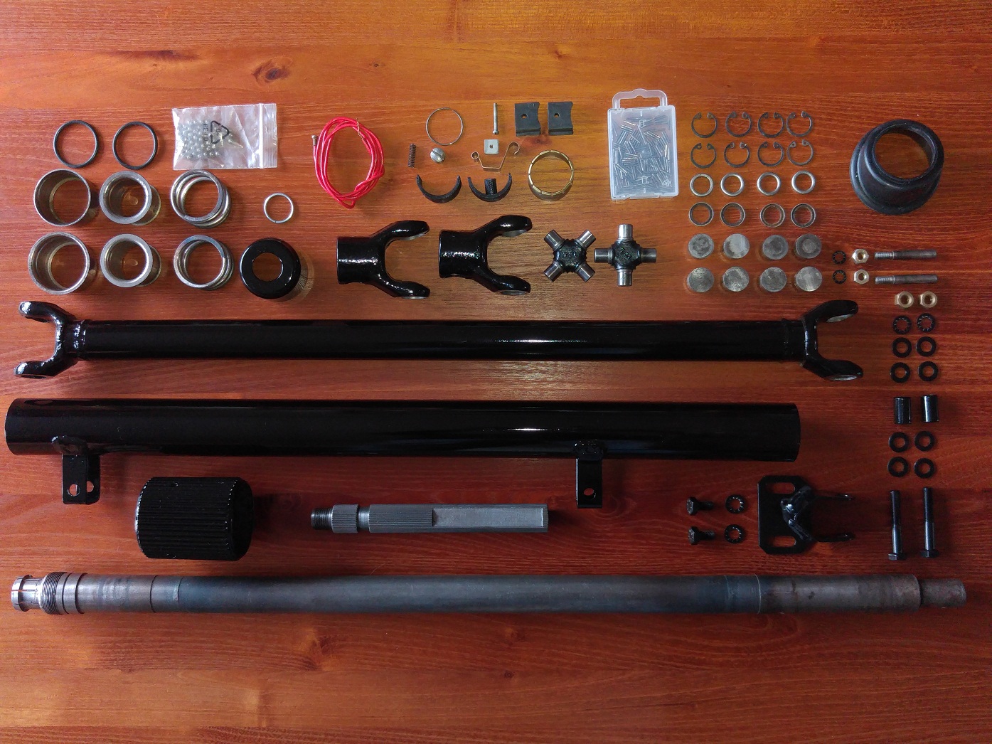
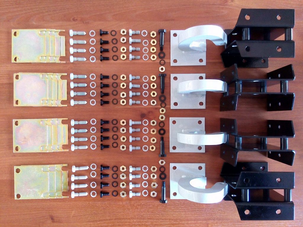
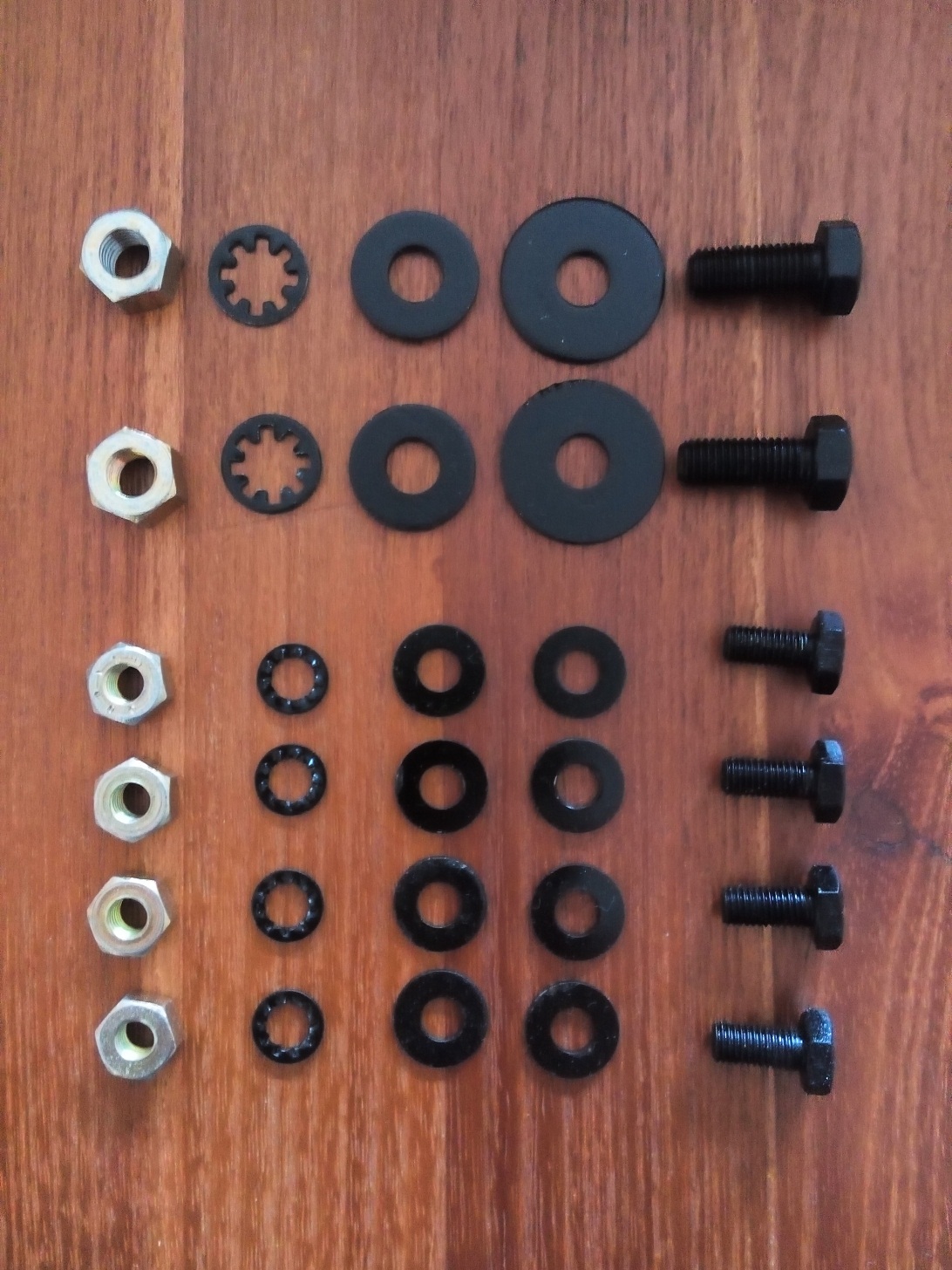
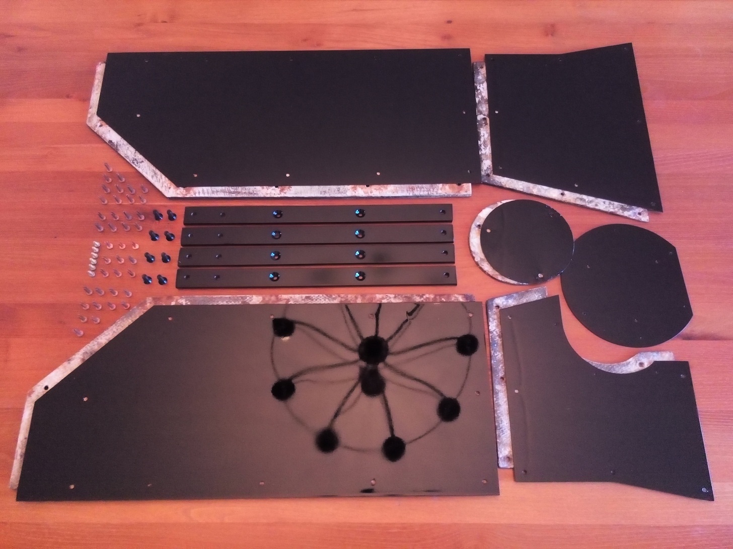
Parts needed to rebuild the heater unit

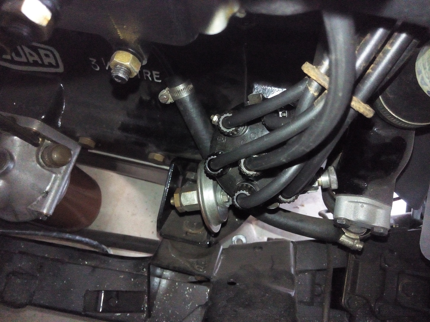
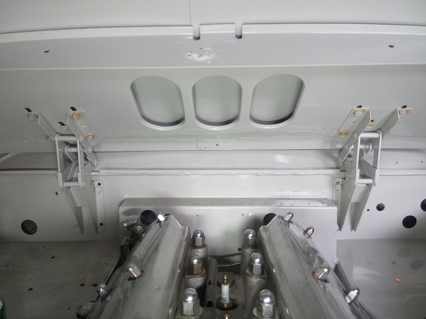
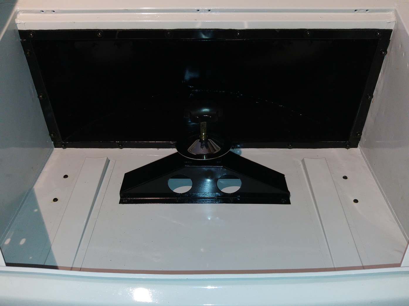
Now that all parts are thoroughly cleaned, painted and retouched everything can be re-assembled again. Also the 12V motor has been tested, after applying some crease inside, it spins without making any noise. (the carbon brushes are OK, and there is no play on the bearings)

 Posted by at 20:20
sep 052018
 

The fairing panel, the connection between the two front wings, has been removed completely because the front wings were also removed.  This piece already shown some cracks on the places where is was welded onto the front wings. Now the front wings are remounted again the fairing panel, after it has been repaired, can also be put back again. To smooth out the surface a layer of lead has been applied, to prevent a tick layer of filler during the paint job.

Front wings without the fairing panel

Fairing panal rewelded onto the front wings

New layer of lead applied to smooth out the surface

New layer of epoxy primer

Bonnet fitment onto the fairing panel

 Posted by at 18:23
mei 202018
 

One of the last parts needed to start the engine is the distribution and ignition. The last parts will be the fuel pump and some small missing parts around the timing and choke functionality.

Parts needed to rebuild the distribution and ignition

During installation of the ignition coil bracket I found out that the right upper corner should have a chamfered edge. This part has been bought new because the original one was missing. With the current shape the throttle axis hits the bracket at the location mentioned before.

The clamp used to fix the distributor on the engine block was also missing. After several attempts, to buy an used or new one failed, I decided to make one myself. The nut and bolt, shown on the left side of the clamp, are reused from a different wrong model clamp.

Distribution parts mounted

Ignition parts mounted


The ignition sequence is 1, 5, 3, 6, 2, 4. Plug number one is at the rear of the engine, number 6 at the front.
Cylinder 1 and 6, 2 and 5, 3 and 4 are moving synchronous. They also switch between the front three cylinders and rear three cylinders between each ignition. (Most probably to get a good distribution of the forces on the crankshaft) So this is the reason the ignition sequence is a bit strange.

 Posted by at 14:37
mei 152018
 

In the last months I have been busy with removing all old layers of paint from the bonnet and front wings. So it is now time to give the bonnet a new fresh layer of paint. In order to ensure that the adhesion of the paint to the aluminum is good, an epoxy primer must first be applied. Secondly a fresh layer of pearl grey paint will be applied.

Parts need for mounting the bonnet

Bonnet painted with epoxy primer on the inside


Now that all individual parts are finished the Bonnet can be mounted onto the body. Next step is the adjustment of the bonnet onto the front wings and body. If these adjustments are all OK the small piece of metal, located between both front wings, can be welled into his place. This will be the last part of the bodywork for the front side of the car.

Bonnet hings mounted between body and bonnet

Bonnet painted on the inside

 Posted by at 21:39
mrt 182018
 

Until now, when the car needs to be moved, I had to turn the wheels by hand. Especially when I need to turning the car around on the street it can be a heavy job. Now that the body has been mounted onto the chassis the steering column can be placed back.

Original steering column inside

Original steering column in engine bay

After cleaning and inspecting all parts I decided to:

  • I will reuse the upper and lower barring (two new 3/16″ steel balls ordered because they where missing)
  • I will reuse the universal joints because the still looks undamaged
  • The rubber grommet needs to be replaced
  • The rubber insulator used between slip ring and steering shaft are made with the help of a 3D printer (They cannot be bough separately)

Parts needed to rebuild the steering column

After mounting everything on the correct place I noticed that the rubber grommet, normally visible from the engine bay, did not came into contact with the outside of the steering column. Therefore I decided to keep it inside of the body, not as it should be, it will keep the air stream outside of the body compartment.

Restored steering column inside engine bay

Restored steering column inside


 Posted by at 20:32
okt 222017
 

Before the front wings can be mounted finally the door hinges must be placed. These hinges are the connection between the front wings and the dashboard strengthener.

Parts needed for the left and right door hinges

 Posted by at 19:27
okt 152017
 

Now the left and right front wings are restored, and the inside has been painted, it is time to place them back onto the body. Although most restorers leave them onto the body en remove the lower part of the front wings to repair the dashside strengtheners, I decided to remove the whole front wings at the place the where originally fixed to the body.

This method has the following advantages/disadvantages:

  • + Removing and mounting can be done by myself.
  • + Cleaning the inside of the front wings is much easier.
  • + Repair and cleaning of the dashside strengtheners is very easy
  • + Afterwards it will be invisible to see they where removed.
  • + During the restoration process it was easier to store them temporarily in the attic.
  • –  Difficult to place the wings back on exact the same spot.
  • –  Lead must be placed back, which can be difficult.

The front wings are welded to the body nearby the front windscreen. Nearby the radiator the front wings are mounted on three places with bolts onto the chassis.

Parts needed to bold the front wings onto the chassis

Now that the front wings are mounted and the front hood is placed, it starts to get the contours of a Jaguar xk140 again.

 Posted by at 14:51
sep 092017
 

The spare wheel tray is the area at the back of the car where the spare tire is stored. This area can be closed with a wooden lid.

The bracket, which is used to secure the wheel firmly, is bolted onto the floor. On the backside of the floor massive steel strips, with threaded holes, are used to reinforce the floor. Between the body and the recess panel (half round shaped part) a small strip of felt is mounted to prevent rubbing of the two separate parts.

 Posted by at 17:16
aug 302017
 

When I bought the car 8 years ago the body was already removed from the chassis. Today they will be reunited again. The chassis was already ready and the body has been finished on the underside in the past few weeks.

Parts needed to mount the body onto the chassis

The previous owner has kept a good administration of where all the distance pieces originally belong.
It is very important that they will be placed back on the exact same place.

This car has 18 places where the body will be mounted unto the chassis;

  • 4 on the Front Wing Support (2 on each side)
  • 4 on the fixed floor (short bolts, with square aluminium distance pieces)
  • 4 on the door sill (medium bolts, with round distance pieces)
  • 2 nearby rear chock absorber (pointed bolts, with round distance pieces)
  • 4 on the rear end of the body (large bolts, with round distance pieces)


 Posted by at 08:25
aug 292017
 

To prevent that the heat from the outlet will heat up the floor, heat shields are provided on the underside. The heat shields are made from asbestos and are covered by a thin layer of aluminium to prevent the asbestos from crumbling. These aluminium asbestos protection plates where corroded and need to be replaced by new ones. The asbestos shields are still in good usable condition and will be reused.


Because the rivets, used to mount the asbestos and aluminium sheets to the steel floor, can only be used one-time I started to search for them on the internet. After some time I discovered a bunch of brand new, by Jaguar so called, “Bifurcated Rivets”

 Posted by at 14:27