apr 272020
 

The air filter, special version for the FHC, was available in the pile of parts belonging to the car. The brackets needed to mount it to the water outlet and to the air inlet where not available and made by myself. I also reshaped the right part of the air filter by removing the lid because it was badly damaged in the past. By removing the lid it could be straighten from the inside which was much easier.

All parts needed for mounting the air filter
The air filter mounted on the carburetors

The air filter will be protected from water and dirt by splash screen.
This splash screen consist of two parts :
– one before the front wheel (protecting the ignition)
– one after the front wheel (protecting the air filter)

Parts needed for the splash screens
Splash screens mounted before the air filter and ignition

 Posted by at 13:31
mei 062020
 
All parts needed to rebuild the doors and lock the battery into position.

To prevent water will reach the battery the openings are closed with a door. On one side the door is hold into position with a metal clip, and on the other side two “dzus” fasteners are used to lock them into there position. The doors are made water proof with by placing a rubber strip on the inside.

The battery is placed onto a rubber block and locked into position with two brass bolts and a metal strip.

 Posted by at 15:35
apr 272020
 

The XK140 Fixed Head Coupe has two batteries one on each side. Each battery is 6V and, because they are used in series, the total voltage will be 12V. (See also Battery Box Right Side)

Due to spilled acid in the past the bottom and some brackets where rotten away completely. So these parts has been replaced with some new fresh sheet metal. Everything is spot welded to each other and, of course, painted black as original.

Parts needed to mount the battery box
The battery box for the right side

We now only need to mount the battery and battery door to close the opening , and to finished off this part. (See Battery Box Doors )

 Posted by at 13:57
apr 272020
 

The XK140 Fixed Head Coupe has two batteries one on each side. Each battery is 6V and, because they are used in series, the total voltage will be 12V.  (See also Battery Box Left Side)

Due to spilled acid in the past the bottom and some brackets where rotten away completely. So these parts has been replaced with some new fresh sheet metal. Everything is spot welded to each other and, of course, painted black as original.

Parts needed to mount the battery box
The battery box for the right side
The right side battery box mounted on the right side of the car

We now only need to mount the battery and battery door to close the opening , and to finished off this part. (See Battery Box Doors )

 Posted by at 13:10
dec 312014
 

This parts covers the flywheel and clutch  located between engine and gearbox. It is also used to mount the starter motor which makes a connection to the ring gear on the fly wheel.

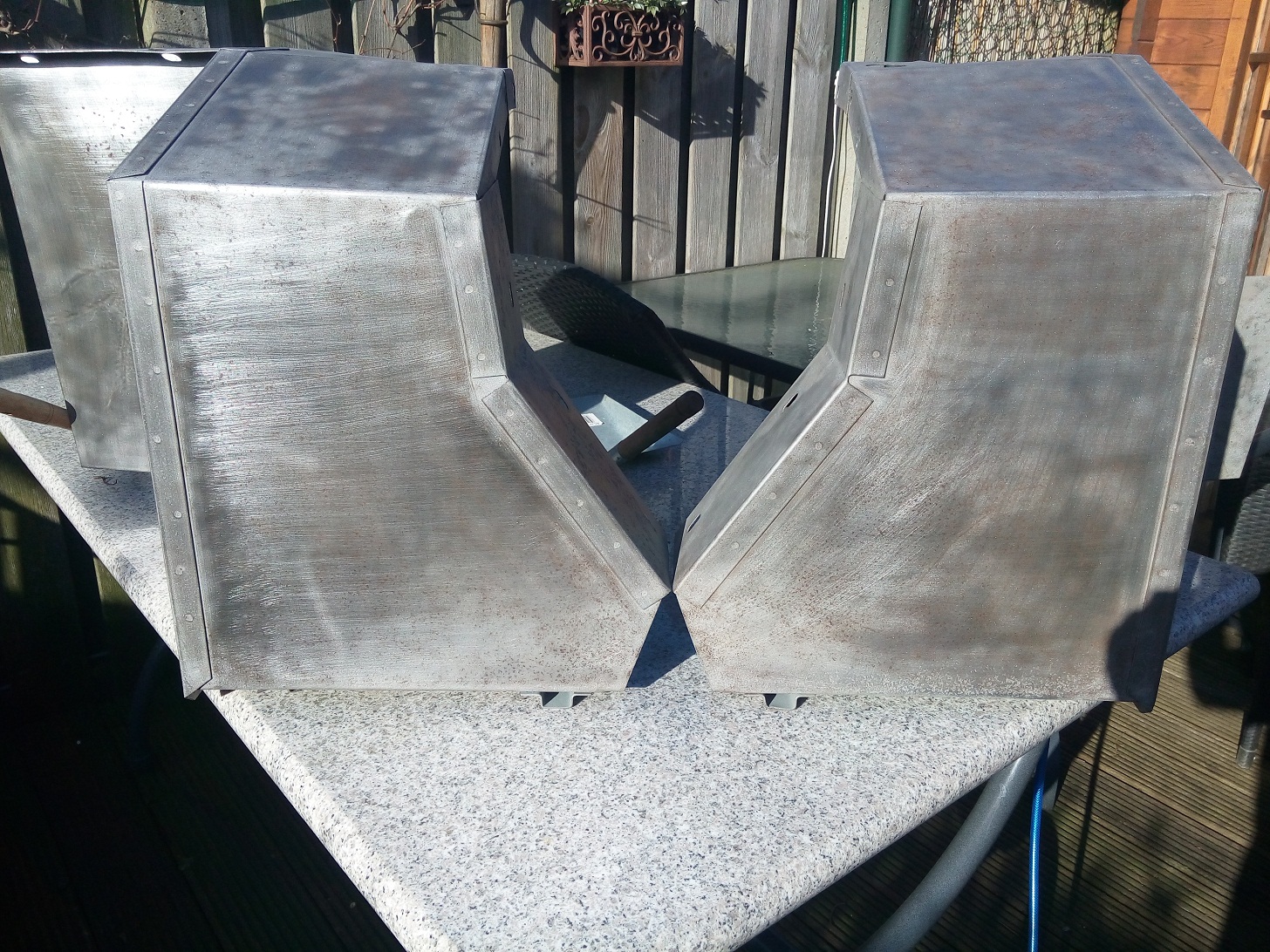
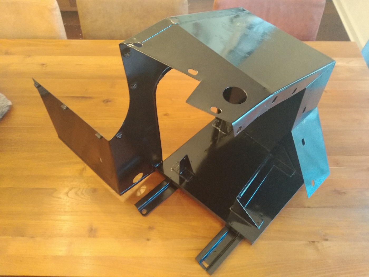
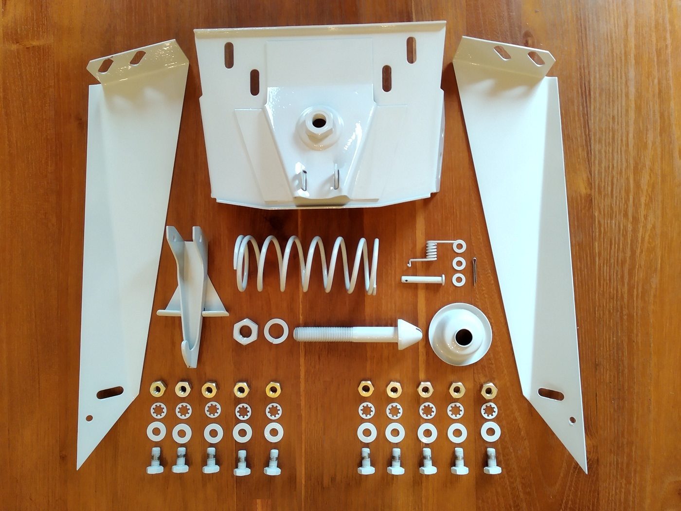
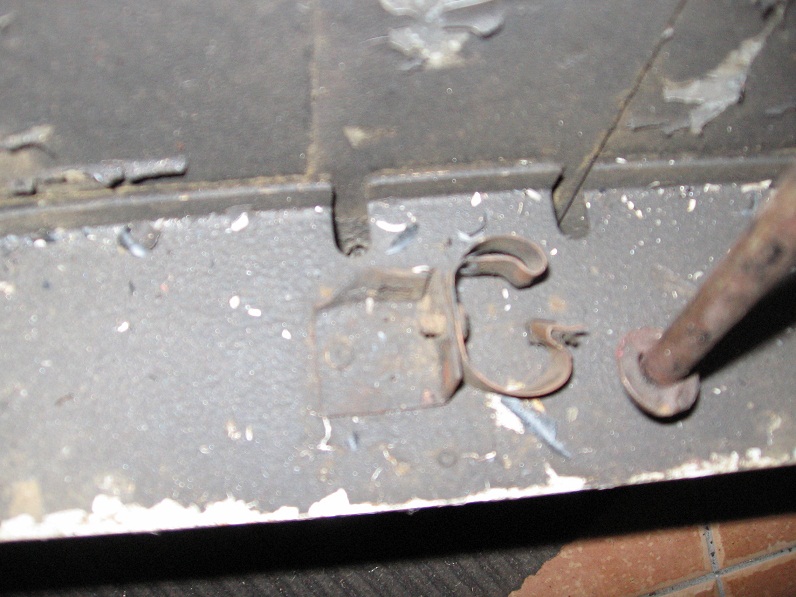
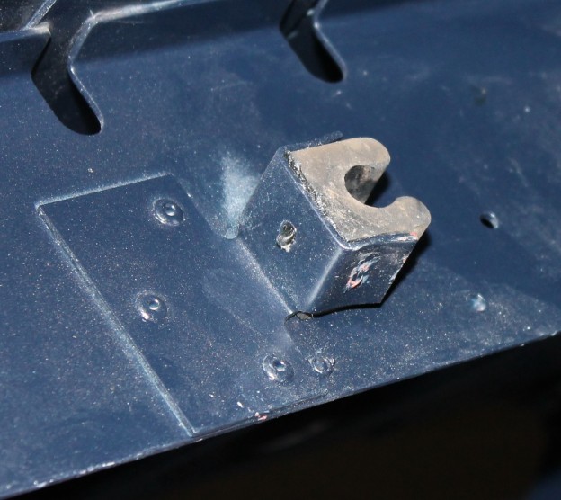
The original bell housing was corroded badly and one of the previous owners has made a square hole in the bottom. Most probably to inspect the clutch or do some kind of repair without removing it from the engine. I found a nice replacement in the UK as can be seen in the next picture.

BellHousingParts

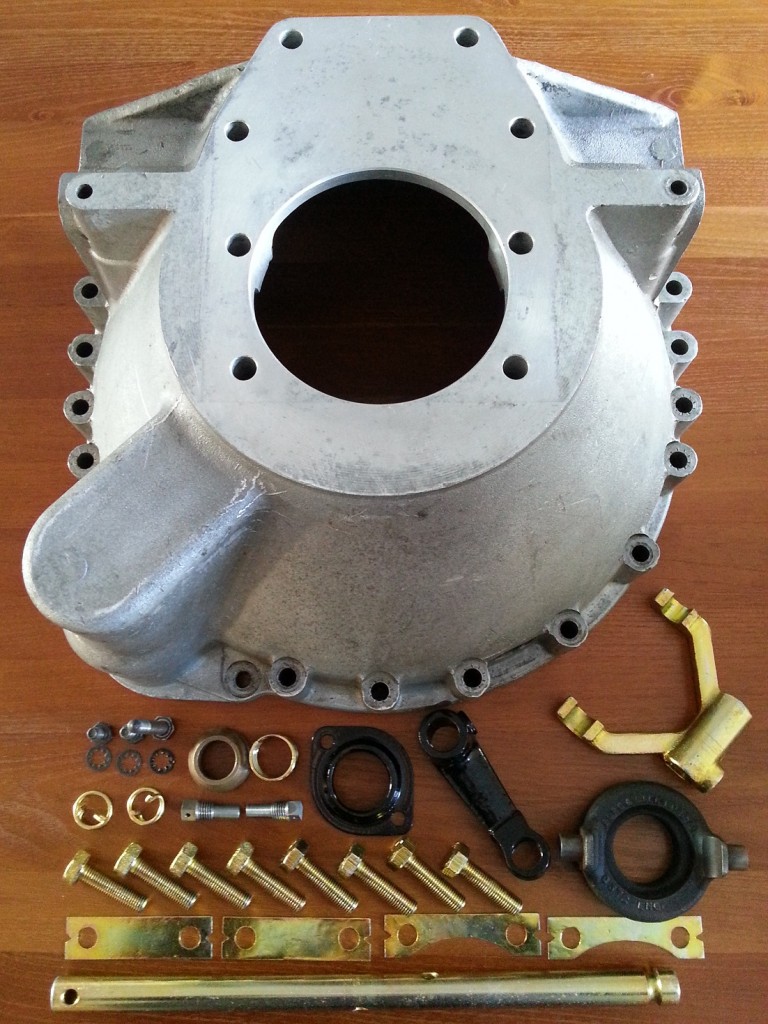
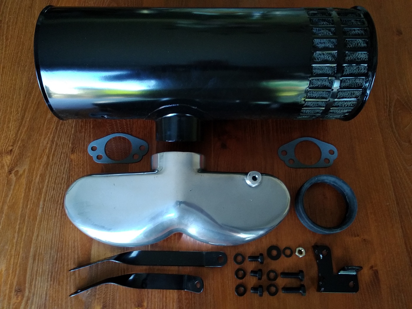
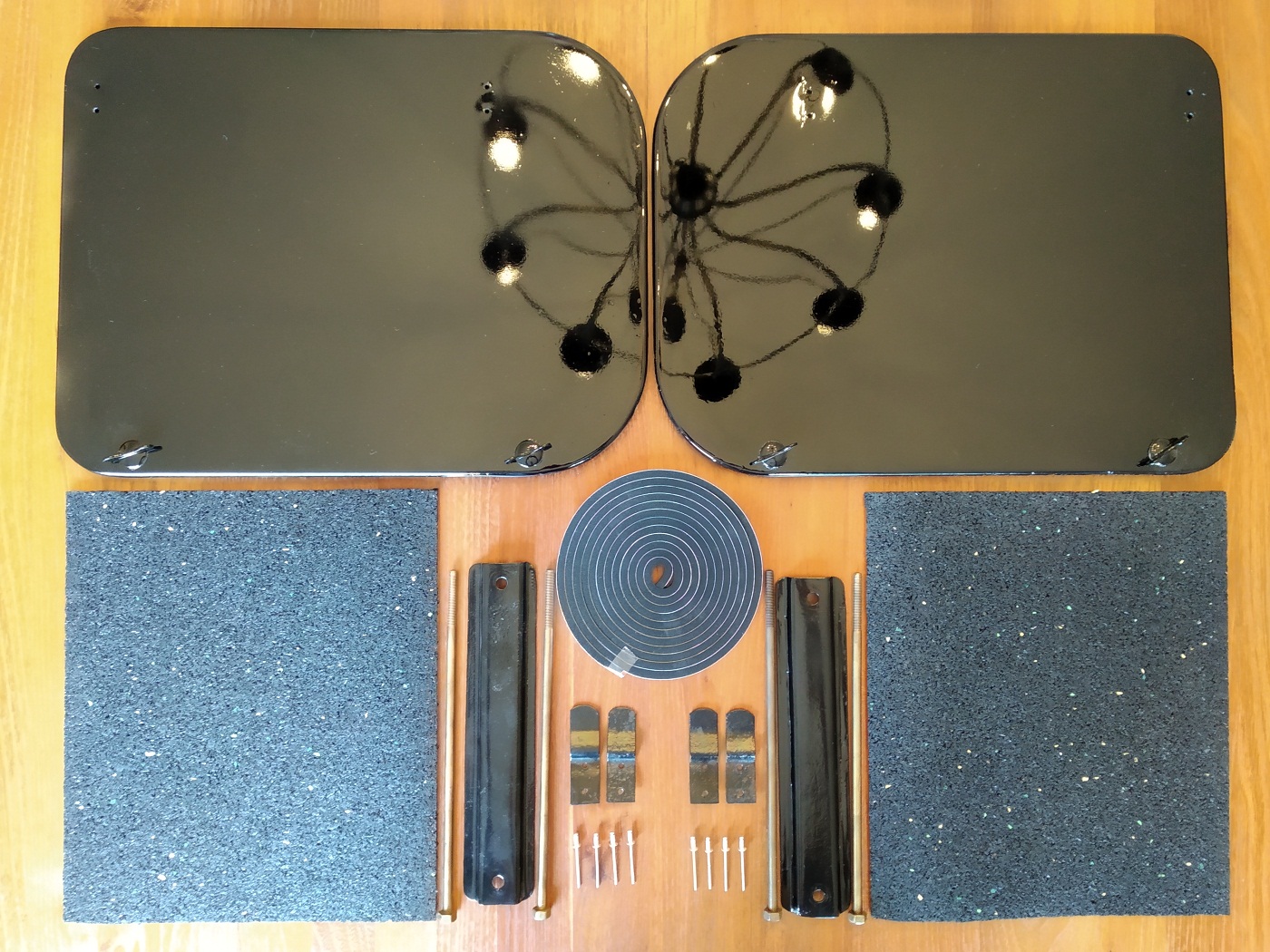
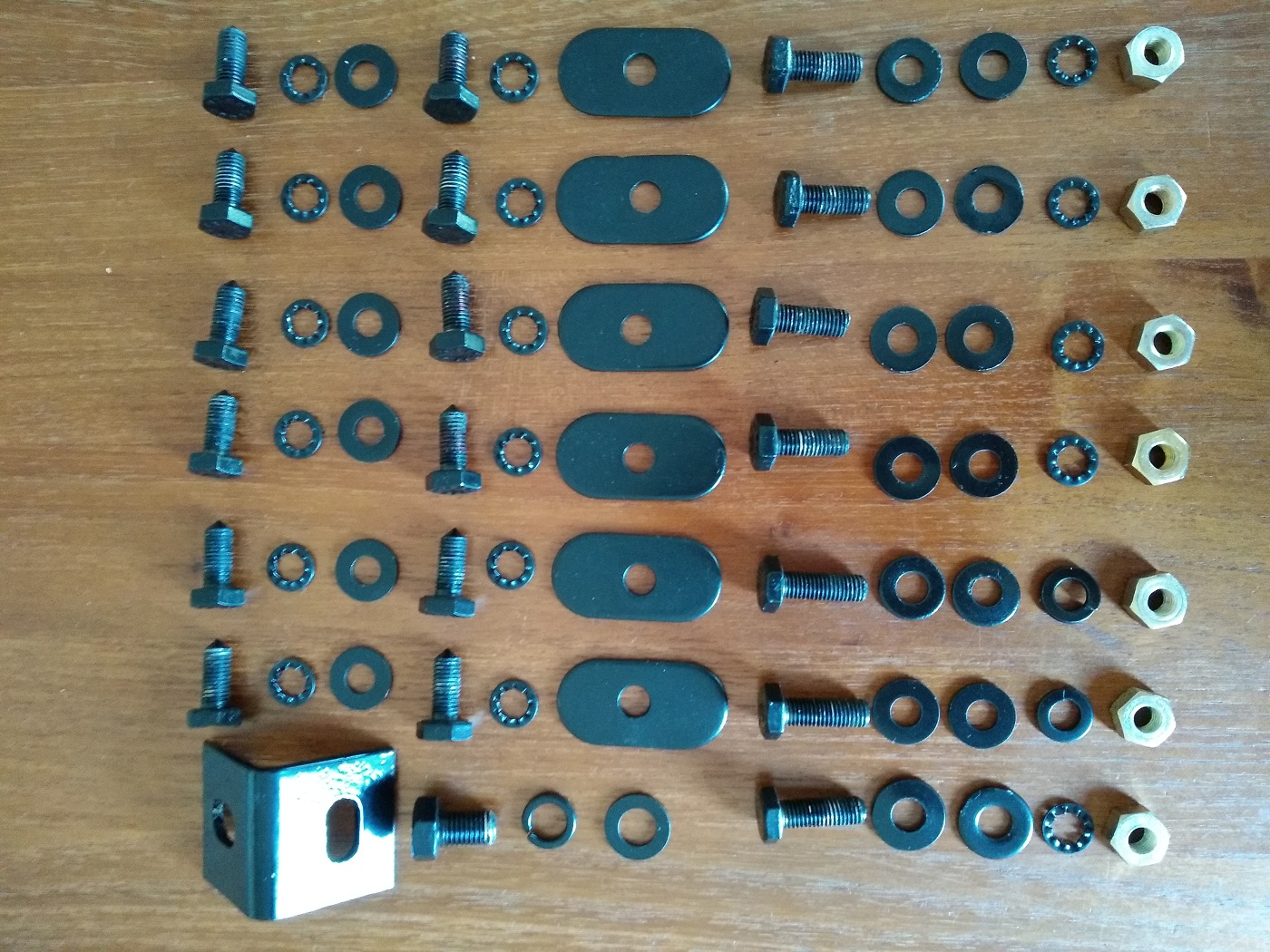
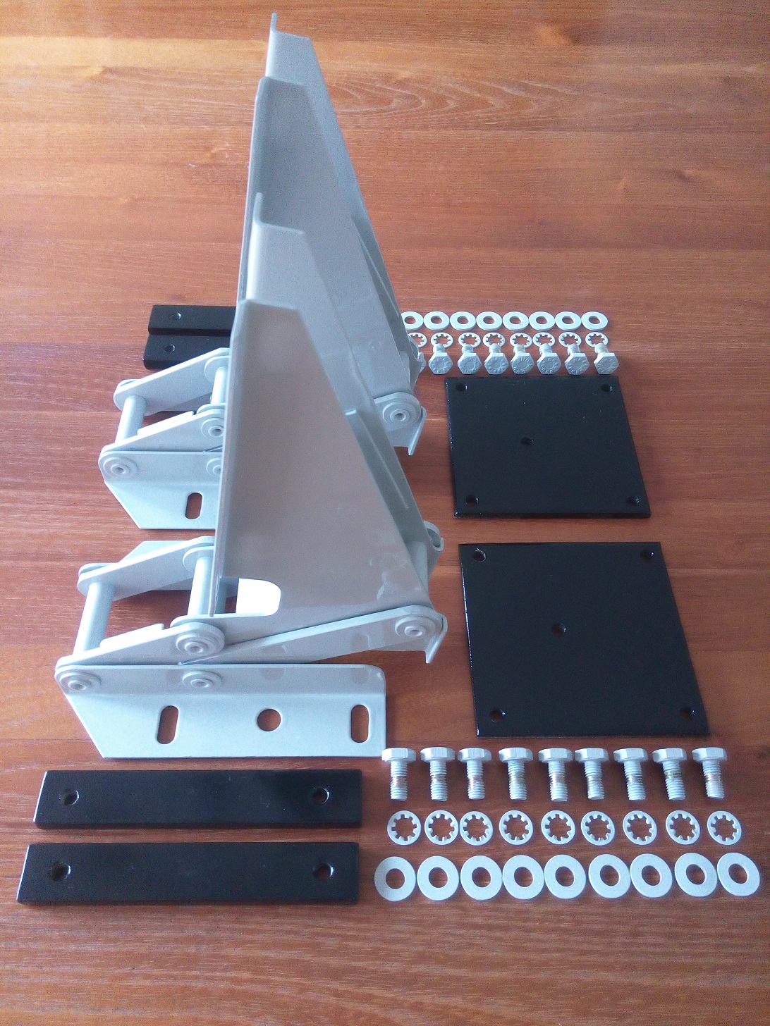
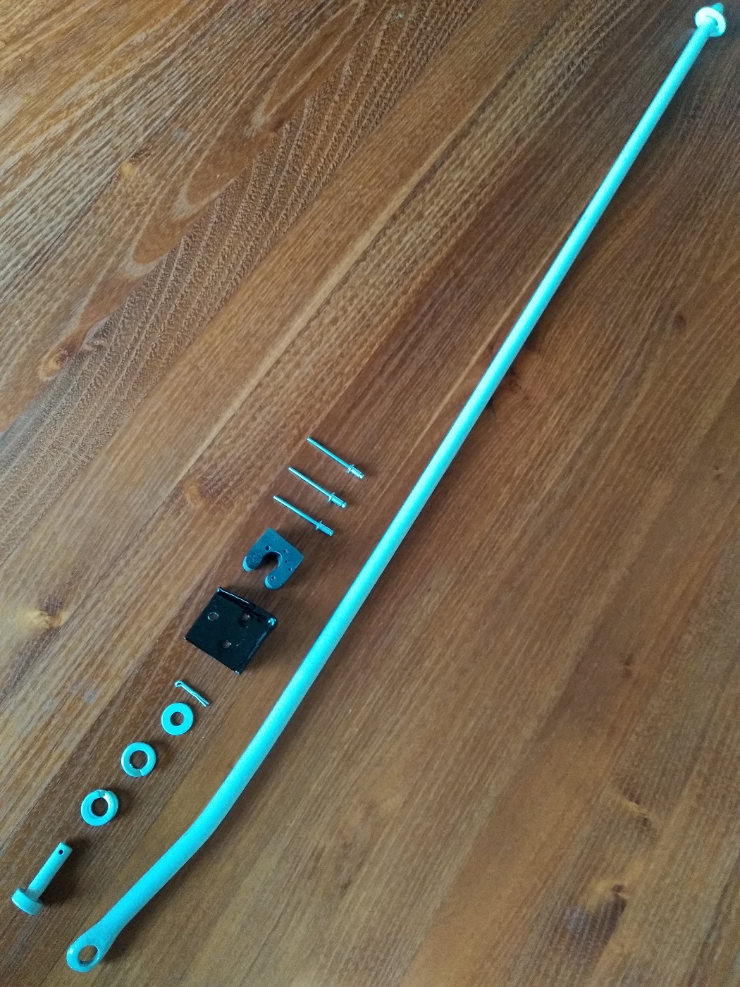
Parts needed to assemble the bell housing

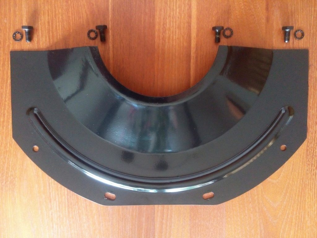
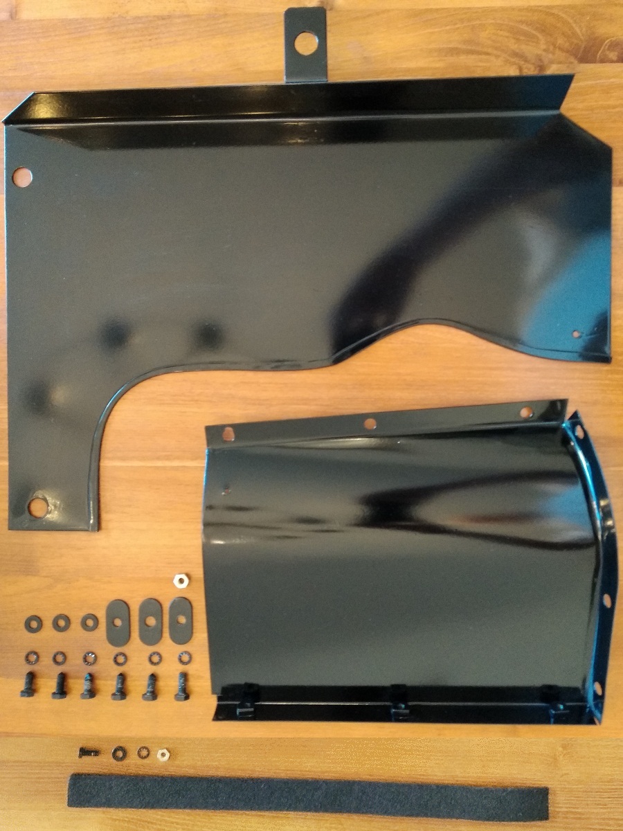
Plate to protect the clutch house internals

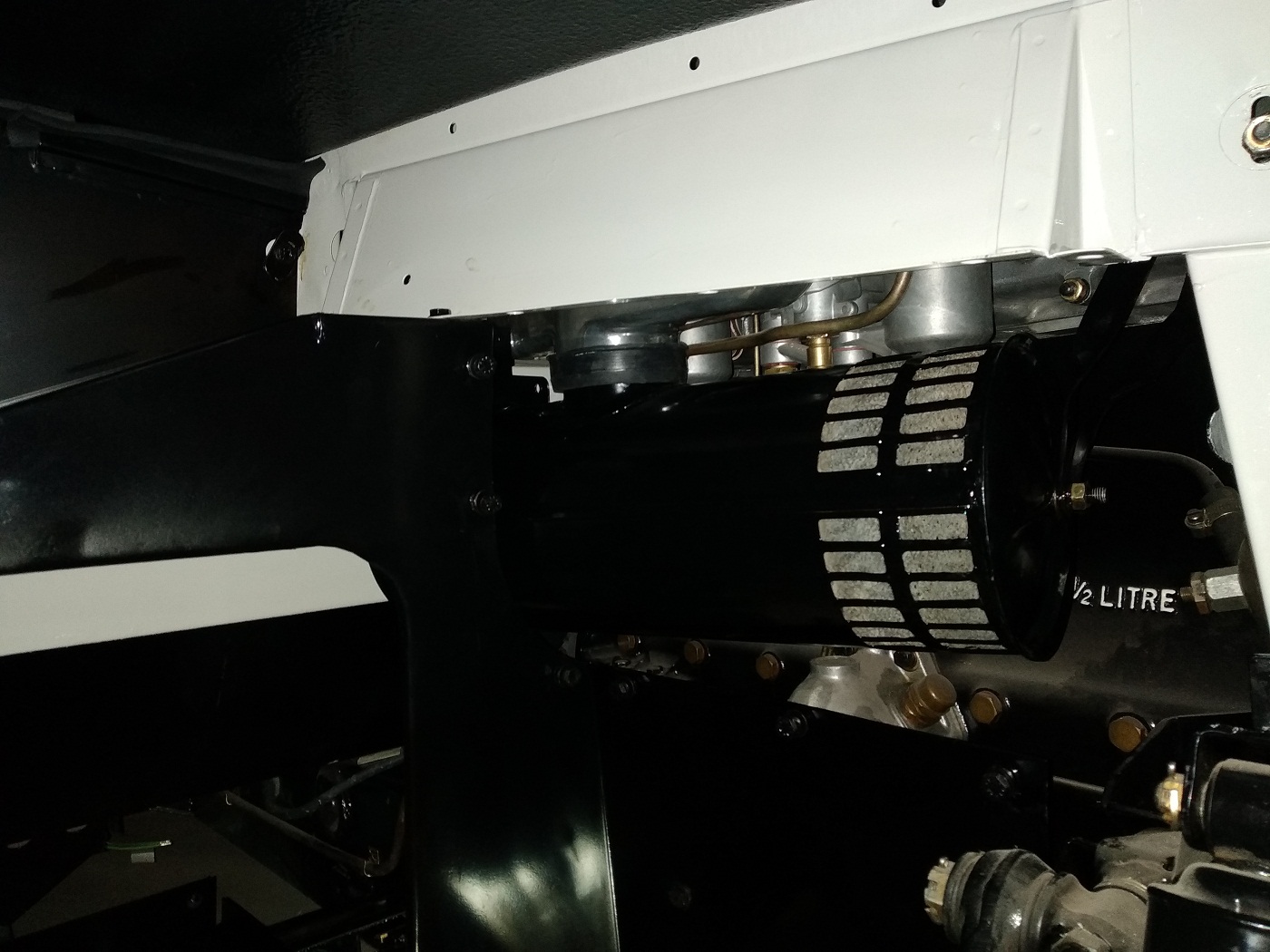
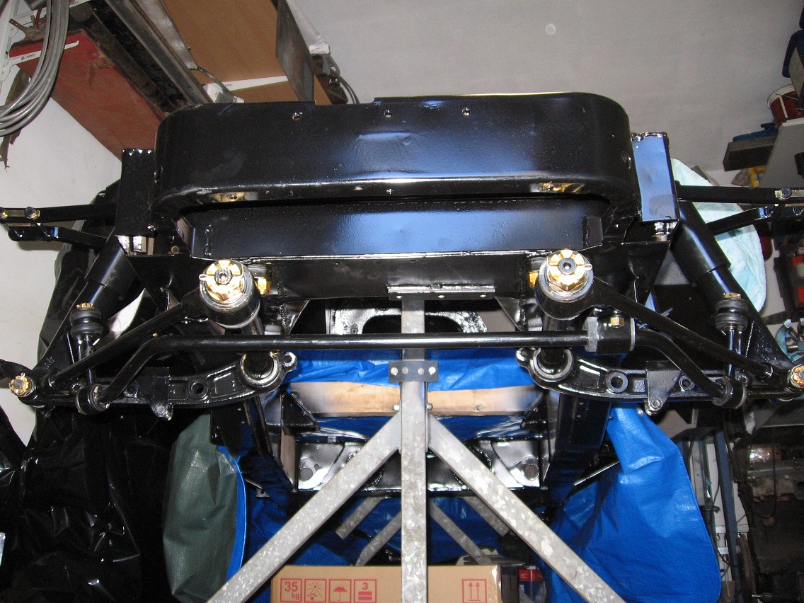
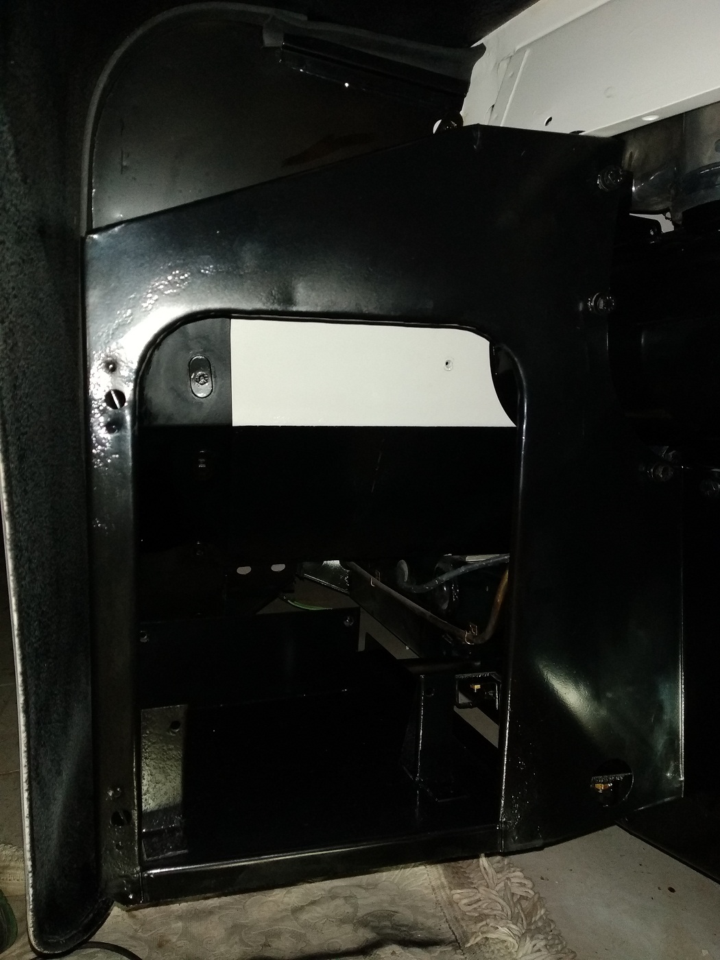
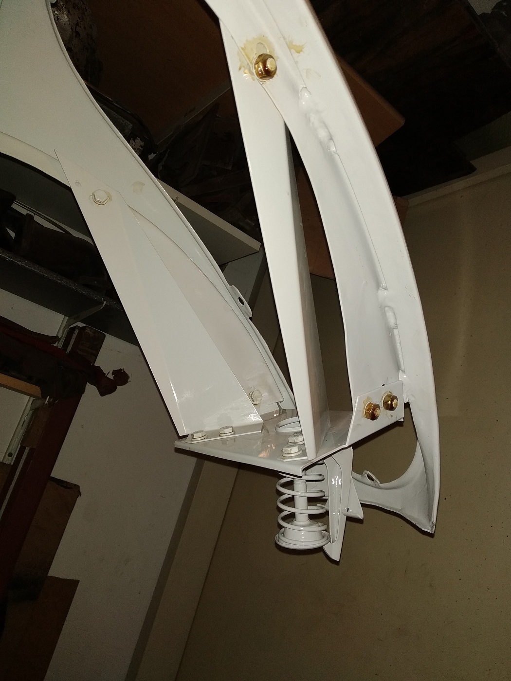
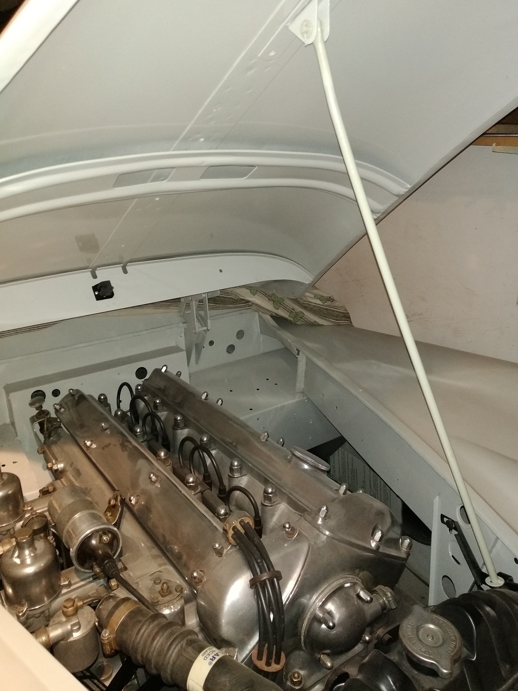
In the next picture the assembled gearbox has been mounted onto the bell housing. The clutch fork and clutch bearing can bee seen on the photo in more detail. The next step is assembling the top cover of the gear box. When this part is finished everything can be bolted, together with the clutch and pressure plate, to the engine. The protection plate must be mounted when the engine and gearbox are bolted together.
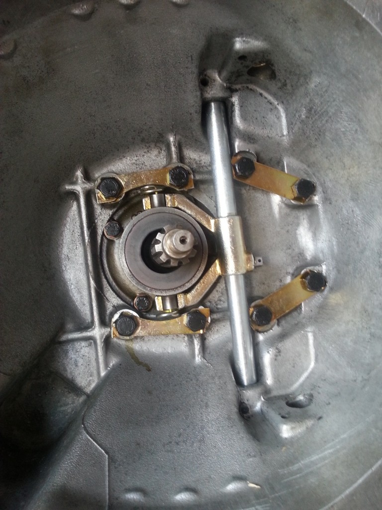
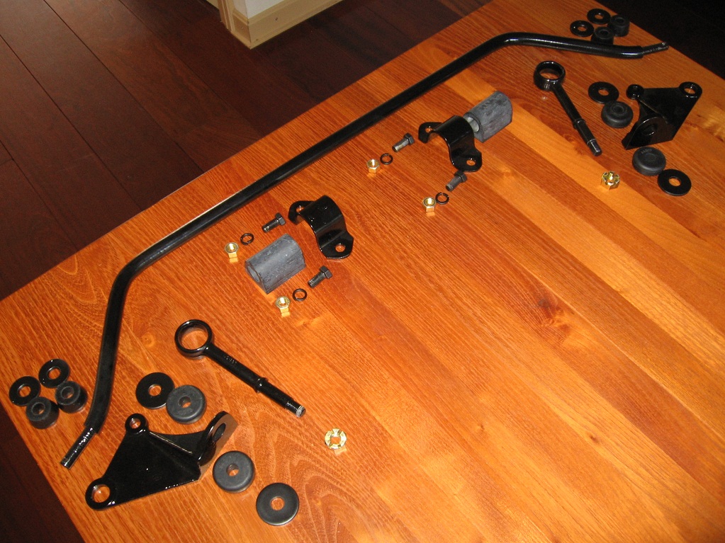
2014-12-29 12.55.04

Clutch fork detail

2014-12-29 12.56.12

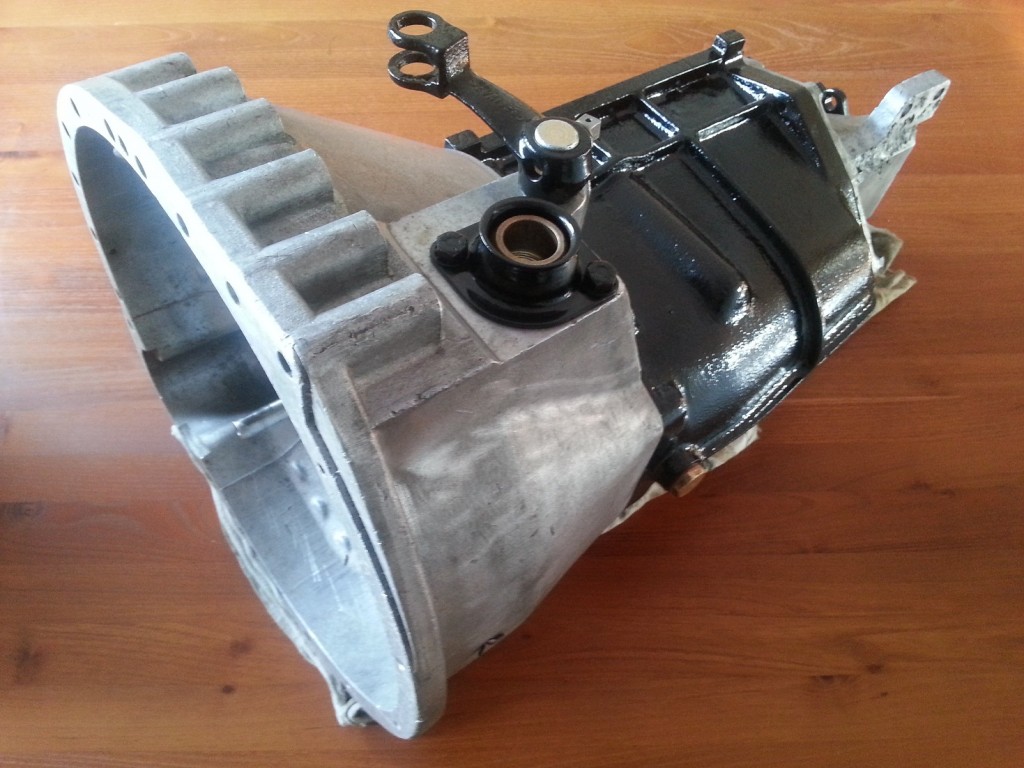
Finished gearbox and bell housing


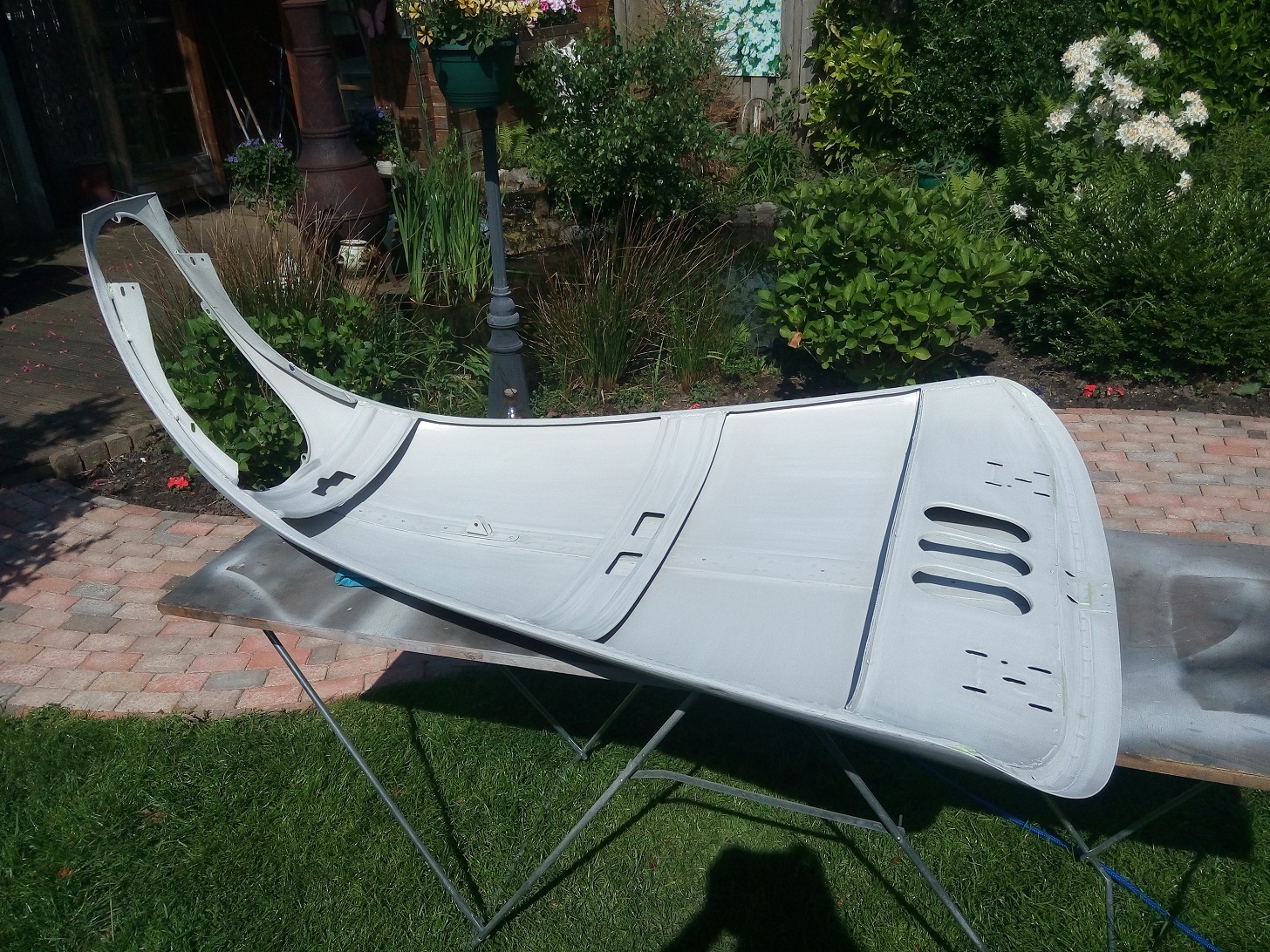
Because the flywheel, pressure and clutch plate can’t enter the bell housing when the cover plate is mounted already, it will be done after it has been bolted to the engine block. This cover plate prevents that water, crease and dirt enters the bell housing and will have a bad influence on the clutch operation.

 Posted by at 12:59
aug 302017
 

When I bought the car 8 years ago the body was already removed from the chassis. Today they will be reunited again. The chassis was already ready and the body has been finished on the underside in the past few weeks.

Parts needed to mount the body onto the chassis

The previous owner has kept a good administration of where all the distance pieces originally belong.
It is very important that they will be placed back on the exact same place.

This car has 18 places where the body will be mounted unto the chassis;

  • 4 on the Front Wing Support (2 on each side)
  • 4 on the fixed floor (short bolts, with square aluminium distance pieces)
  • 4 on the door sill (medium bolts, with round distance pieces)
  • 2 nearby rear chock absorber (pointed bolts, with round distance pieces)
  • 4 on the rear end of the body (large bolts, with round distance pieces)


 Posted by at 08:25
mei 152018
 

In the last months I have been busy with removing all old layers of paint from the bonnet and front wings. So it is now time to give the bonnet a new fresh layer of paint. In order to ensure that the adhesion of the paint to the aluminum is good, an epoxy primer must first be applied. Secondly a fresh layer of pearl grey paint will be applied.

Parts need for mounting the bonnet

Bonnet painted with epoxy primer on the inside


Now that all individual parts are finished the Bonnet can be mounted onto the body. Next step is the adjustment of the bonnet onto the front wings and body. If these adjustments are all OK the small piece of metal, located between both front wings, can be welled into his place. This will be the last part of the bodywork for the front side of the car.

Bonnet hings mounted between body and bonnet

Bonnet painted on the inside

 Posted by at 21:39
apr 292020
 

This mechanism is used to open, close and lock the bonnet. With a cable, operated from the dash, this mechanism can be released. To prevent the bonnet jumps open during driving an extra hook is mounted which must be pulled forward by hand before the bonnet can be opened.

Parts needed to rebuild the bonnet catch and release mechanism

The metal strips between the bonnet and catch plate are installed to divert the air flow. The radiator is only 16″ wide while the opening in the grill is only 8″wide. The “air deflectors” should make it possible to cooling down the whole radiator surface. This was not an optimal solution because most cars suffer from overheated cooling systems, during hot summer days.

Bonnet catch and release mechanism with the air deflectors

 Posted by at 15:12
apr 272020
 

The bonnet prop consist of two brackets and a rod. When the bonnet is open the rod is place on the bracket nearby the radiator. When the bonnet is closed the rod is placed in the rubber clamp in the middle of the bonnet nearby the hings. (See photo)

Parts needed to rebuild the bonnet prop

Bonnet prop mounted

On internet I see different type of clamps for the “closed position”. But the original pop rivet holes are different and the original bracket looks original to me. I removed the metal clip (left side) and replaced it with a rubber clip, which I removed from a new one bought on internet (right side)

Original one mounted on my car
New ones found on internet

 Posted by at 20:08